• HOME
  • Projects
  • Concepts
  • Design Media
  • Resume
  • Blog
Menu

ADRIANA L. ZARRILLO

AIA, NCARB, LEED AP BD+C
  • HOME
  • Projects
  • Concepts
  • Design Media
  • Resume
  • Blog

Integrity of Concept + Thoughtfulness in Development = Sophistication of Design.

4000 Connecticut Building Renovation

with VOA Associates
as Project Architect / Project Designer

location: Washington, D.C.
typology: Building Renovation / Repositioning
size: 1 mil GSF / 650,000 USF
status: construction documents

The 4000 CONNECTICUT Building Renovation is a holistic exercise in rebranding and repositioning of the facility in the Washington DC real estate market.  Originally designed by John Andrews and constructed in 1984 as the headquarters for the Intelsat Corporation, the building was purchased by a private developer, 601 W LLC, in 2012.

The original design is composed of a series of octagonal pods, ranging from 4-7 floors.  Each quartet of pods surrounds an equally impressive atrium with a central concrete spiral stair and bridges extending out to each of the floors. There are a total of 14 pods and 5 atriums.  As was the brutalist style at the time, each of the three entrances to the building are swathed in a sea of paving, but none so much as the Connecticut Ave entry.

Connecticut Avenue is one of the major thoroughfares of DC and its stark entrance is a notorious blemish on the streetscape.  Re-envisioning the plaza and entry sequence is an important exercise to re-engage the building in the community and its surrounding park-scape.  In conjunction with Lee and Associates Landscape Architects, I developed a plaza and new entry façade to engage the public realm. 

The existing interior atriums include a  series of water features and green spaces that I envisioned spilling out into the plaza.  Updating the curtain wall façade, creating a canopy and an entry portal were all elements used to mark this as the front door of the building.  Additionally, the creation of water features and gentle swaths of planting mitigated the harshness of the existing plaza.

The building as a land lease on State department owned land is subject to review by the US Commission of Fine Arts as well as the National Capitol Planning Commission.  I shepherded the design through this process and ultimately to approval.

Another unique component of this project is known as the Moon Garden.  The moon garden is a space located at the uppermost level of the central atrium and is isolated by its six foot elevation difference from the rest of the spaces.  This unique space surrounded by planting offers fantastic views both out and up. Part of my efforts were to aimed at preserving its specialness while also reducing its isolation from other spaces in the building.  Upgrading the planting to taller more lush species, and adding a lighting component allows the space to be used in the evening and offer some acoustic mitigiation.  The existing space is relentless in its gray color palette and hard materials. Adding in some built-in woodwork and upholstered seating as well as wood wall cladding softens the space without losing its flexibility.

Access is also an issue.  I developed a concept for bridges that would float between the moon garden space and an existing light well.  These bridges would be floored with slate foreshadowing the moon garden and sidewall would be clad with backlight glass to create a soft glow.

Additionally, the egress stairs for this building are cylindrical glass block clad elements prominently located at the cores between pairs of pods.  The towers are set upon a concrete plinth housing mechanical and electrical equipment for each area. Originally, these plinths created shallow water features around the towers, however, over time, maintenance and leakage issues resulted in their draining and non-use.  I conceptualized the reuse of these areas as additional user amenity space by repurposing them as roof terraces.   


RENDERING
RENDERING

Proposed Connecticut Avenue two-tier plaza.

EXTERIOR RENOVATION DIAGRAMS

Selective demolition, structural enhancement and finish enclosure diagrams.

PLANS | SECTIONS
PLANS | SECTIONS

The section shows the transition between the existing storefront and the new components.

FINISH PALETTE
FINISH PALETTE

Exterior and vestibule finish palette.

'MOON GARDEN' PROPOSED FLOOR PLAN
RENDERING
RENDERING

Moon Garden seating and planting.

RENDERING
RENDERING

Moon Garden pre-function rendering showing the connections to surrounding spaces.

PROPOSED ROOF DECK
PROPOSED ROOF DECK

Proposed roof deck design for all mechanical spaces outboard of building footprint.

District of Columbia Jewish Community Center

with VOA Associates
as Project Architect / Project Designer

location: Washington, D.C.
typology: Building Renovation
size: 50,000 SF
status: concepts

The DCJCC has become one of the most popular community centers in NW Washington DC.  Its programs include art workshops and theater, recreation sports and gym facilities, early childhood development and various other activities.  As the population in DC grows, so does the need for these types of facilities.  The DCJCC has specifically seen a huge rise in demand for early childhood development classes and afternoon daycare services. 

The center is a 4 level neo-classical building located at the corner of Q Street and 16th Street with an adjacent on grade parking area.  The main entry has been relocated from the grand stair and two story lobby to the side entrance for security purposes. 

Two concepts were conceived for the renovation of this facility.  One focused on the reorganization of program and space while the second included the addition of a new facility over the parking lot. The second scheme would increase the square footage of the building by approximately 10,000 SF.

The major difficulty in the existing building is the scattering of program throughout the facility. Gym members float between the basement and third and fourth levels depending upon their workout activity. Locker room facilities and the pool are located in the basement, while weight lifting equipment is on the fourth floor and the cardio classrooms are on the third floor. The same scenario holds true for the childcare functions.  One of the crucial design exercises was to redesign the circulation and create appropriate adjacencies between groups of similar programs and uses. Another important exercise was reviewing the usage and functionality of the existing spaces and how these could be improved to create more flexible, successful and better utilized spaces. Lastly, and especially true for non-profits, the estimated cost for these renovations and viable phasing options is key.  The Board of the DCJCC concurred with the above assessments and has begun fundraising efforts.

The series of blue colored diagrams define the conceptual phasing plan for reorganizing the program within the existing footprint.  The magenta colored plans describe the alternate option, not only reorganizing within the footprint but also increasing the footprint.

In both schemes, the focus was grouping the childhood development activities into the area adjacent to the parking lot. Existing classrooms were already located in this zone and the seldom used racquetball courts above would be converted into classrooms, creating larger flexible spaces for indoor play. An additional glass egress stair would slide into the slot between the parking and existing building providing the required capacity for the additional classrooms. It would extend to the roof where a much needed outdoor play area would be sited on the roof.  In addition to the increased program areas, the building also needs major upgrades to the MEP infrastructure, additional toilet rooms and a catering pantry and kosher kitchen facility.

The most important design component for the DCJCC Board is the conversion of the basketball gym. Renovating this two story space into a multipurpose space would provide greater flexibility for other activities like theater practice, movie nights, banquets and other community functions. The challenges are providing access into the space from the upper level and lobby, developing a strategy for a movable seating system and evaluating the sight lines for a screen wall/stage area on one side. Referring to the images on the left, I created a series of diagrams to show the flexibility of this suggestion to the client.

SCENARIO 01
SCENARIO 01

Plans for phasing a renovation within the existing footprint.

SCENARIO 02, B1
SCENARIO 02, B1

New proposed basement floor plan with a connection to the new structure.

SCENARIO 02, L1
SCENARIO 02, L1

The different color hues represent the potential work phasing for cost and to maintain building operability.

SCENARIO 02, L2
SCENARIO 02, L2

Slab infill of 4 racquetball courts would create 8 new classrooms.

SCENARIO 02, L3
SCENARIO 02, L3

The new structure would be developed at level 03 to maintain the parking below.

SCENARIO 02, L4
SCENARIO 02, L4

The new structure would house additional classrooms, toilet facilities and a large indoor play area.

SCENARIO 02, L5
SCENARIO 02, L5

The roof of the new space would be outfitted as an outdoor play area and community garden.

SCENARIO 02
SCENARIO 02

A new glass enclosed egress stair would create the bridge between old and new construction.

 The existing basketball court would be renovated into a multipurpose space with telescopic seating and updated A/V controls for presentations and productions. 

The existing basketball court would be renovated into a multipurpose space with telescopic seating and updated A/V controls for presentations and productions. 

Turkish-American Community Center

with Fentress Architects
as Project Architect/BIM Coordinator

status: under construction
location: Lanham, MD
typology: cultural
size: varies


The Turkish-American Community Center is a six building campus that was commissioned by the Turkish Embassy as an outreach to its community away from home. The project is composed of a mosque, a Turkish bathhouse, a cultural center, a fellowship hall and a guest house all connected by a series of landscaped paths and plazas over an underground parking garage. The buildings are designed  in Turkish vernacular architecture and adhere to the religious requirements of each type of building.

At the time of award, the project had already undergone a schematic design phase with HASSA. HASSA continued to work as a consultant and provided the artisans for the specialty ornamentation.

Fentress Architects, the architect of record, researched and solved code issues, created specifications, conducted product research and created documentation for permitting and construction.
As the job captain and BIM coordinator I worked on all six buildings and organized and coordinated information between Fentress, the consultants and our design build partner.

MASTER PLAN
MASTER PLAN

The campus is composed of 5 buildings on a central plaza and connected together through an underground parking garage.

TURKISH BATH
TURKISH BATH

The Turkish Bath sauna and resting spaces were built above ground, while the majority of the other recreation center spaces extend up to 3 stories below grade.

 Programmatic arrangements per the client's request required special variances.

Programmatic arrangements per the client's request required special variances.

FELLOWSHIP HALL
FELLOWSHIP HALL

The Fellowship Hall, used for meals and catering, included fine vernacular wood detailing of the front loggia and openings. 

MOSQUE
MOSQUE

The scope of finishes on the Mosque was crucial because a number of elements were to be specially created by Turkish artisans.

 All of the domes except the largest (with a 60 FT diameter) were formed by foam formwork.

All of the domes except the largest (with a 60 FT diameter) were formed by foam formwork.

National Geospatial-Intelligence Agency

with RTKL Associates
as Architectural Staff / Designer

location: Fort Belvoir, VA
typology: office building
size: 5.1 mil SF campus / 2.1 mil SF office
status: construction complete

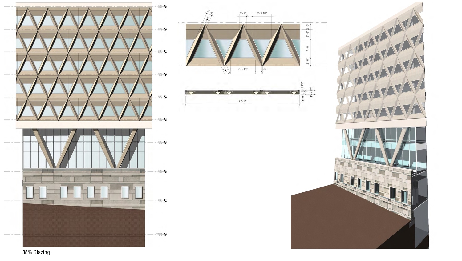
The NGA campus is comprised of five buildings with an office space component of 2.1 million square feet. The master plan situates the office building on the center of a plateau overlooking a river. Two gently curved office space bars enclose an eight story, seven hundred foot long atrium and houses a variety of building amenity space. The surrounding structures as well as the landscape forms are organized around the radial geometry of the atrium. The organization and detailing of the atrium floor was inspired by a dry creek bed visage.  The naturalistic idea infused itself into all aspects of the project, including the hierarchy of the elevations. The facade composition is split between the idea of the terrestrial and the celestial, representing the mission of NGA in its earthly location. The lower portion of the building is  composed of precast panels creating a rusticated plinth. The upper body of the building is comprised of a series of brilliantly white angled precast panels.  The color and detailing of the panels inspires a lighter feel than the darker base. A delicate curtain wall system with metal clad 'V' shaped columns separate and act as the transition between the two architectural worlds. The terminus of each office bar is clad in glass to allow for expansion in the future.

Supporting the lead architect, I began working on this project in the concepts phase by participating in master plan design charrettes, creating building massing studies, site circulation diagrams and site research.  I continued working on the project focusing on the exterior enclosure expression and the interior base building infrastructure. I was instrumental in designing and modelling the precast skin module which won a design award in 2012.

ILLUSTRATIVE SITE PLAN
MODEL IMAGE
MODEL IMAGE
ELEVATIONS
ELEVATIONS
MOCKUP | SECTION | COLOR ITERATIONS

The colored precast base iterations and mock up panels.

BASE CONCRETE PANELS

The panels were coordinated to create somewhat varied color and pattern.

FACADE STUDIES
FACADE STUDIES

The triangular patterned was developed with the percentage of natural light they would allow in mind.

MOCK UP DETAILS
MOCK UP DETAILS
WIRE MODELS
WIRE MODELS

Wire model image of different angles of the building were used to understand the perception of the geometry.

MASTER PLAN MODEL
MASTER PLAN MODEL

Headquarters of the 82nd Airborne Division

with Fentress Architects
as Job Captain / Project Designer

location: Fort Bragg, NC
typology: military headquarters
size: 100,000 SF
status: construction complete

The 82nd Airborne Command and Control Center in Fort Bragg North Carolina was a joint venture with Fentress architects as the primary designer and architect of record for the exterior enclosure, surrounding landscape and ceremonial areas and major public spaces. The previous facility was dated, not environmentally friendly and lacked the presence on base that the 82nd Airborne Division required.

The project site is located on Fort Bragg adjacent to a water tower and deteriorating parking lot. Our concept was based around three major ideas; first, to reorient the parking and entry sequence. Second, to landscape the surrounding site creating a seamless transition from the exterior spaces to the interior sequence. Third, to create an exterior expression that would both refresh the image of the Airborne Division as well as fit within the established design guidelines of the base.

The building massing is organized into three sections. The main entry sequenced starts in the administrative portion of the building. This zone is three levels with significant articulation starting with a battered base, ending with an ornate eyebrow and modularized in between by a pattern of reveals and brick in-lays. The back of the building is a one level zone that houses the command center and required equipment rooms. This area of building facade exercises the same type of elements (brick in-lay and reveals) but simplifies the articulation to hint at bias of the program beyond and mimic the rhythm of the windows above. These two parts are joined together by a linear circulation zone bisecting the project. These programmatic elements (stair towers and corridors) are defined by a heavy use of brick and brick patterning as well as the substitution of curtain wall for individual windows.

The materials and colors used on the exterior expression were drawn from the palette of the base standards and the unique maroon color and “AA” emblem of the 82nd. The entry sequence begins with a series of stone markers flanking the entry walk and transitions into a wood paneled accent wall that reaches the full three levels of the atrium and dies into the skylight at the roof. The detailing of the skylight and the glass monumental stair were both representational of the 82nd Airborne’s renowned paratroopers as well as a design element that offered relief to relentless 8’-6” ceiling heights. The third level program, housing mostly workspaces of high ranking officers, offers an outdoor patio that is also accessible from the major conference room as well.

I helped pursue this project in the proposal phase and after award acted as the project architect, managing consultants, working with the client and our design-build partner and producing all the drawings.

ILLUSTRATIVE SITE PLAN
ILLUSTRATIVE ELEVATION STUDIES
EXTERIOR ELEVATION | SECTION
CONSTRUCTION DOCUMENTS

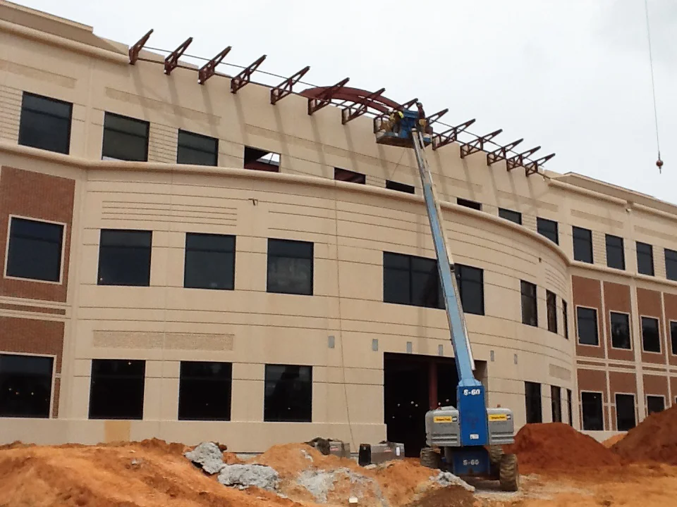
Exterior construction detailing with steel structure and tilt-up precast panels.

CONSTRUCTION PHOTO
CONSTRUCTION PHOTO

Curved entry and canopy framing.

CONSTRUCTION PHOTO
CONSTRUCTION PHOTO

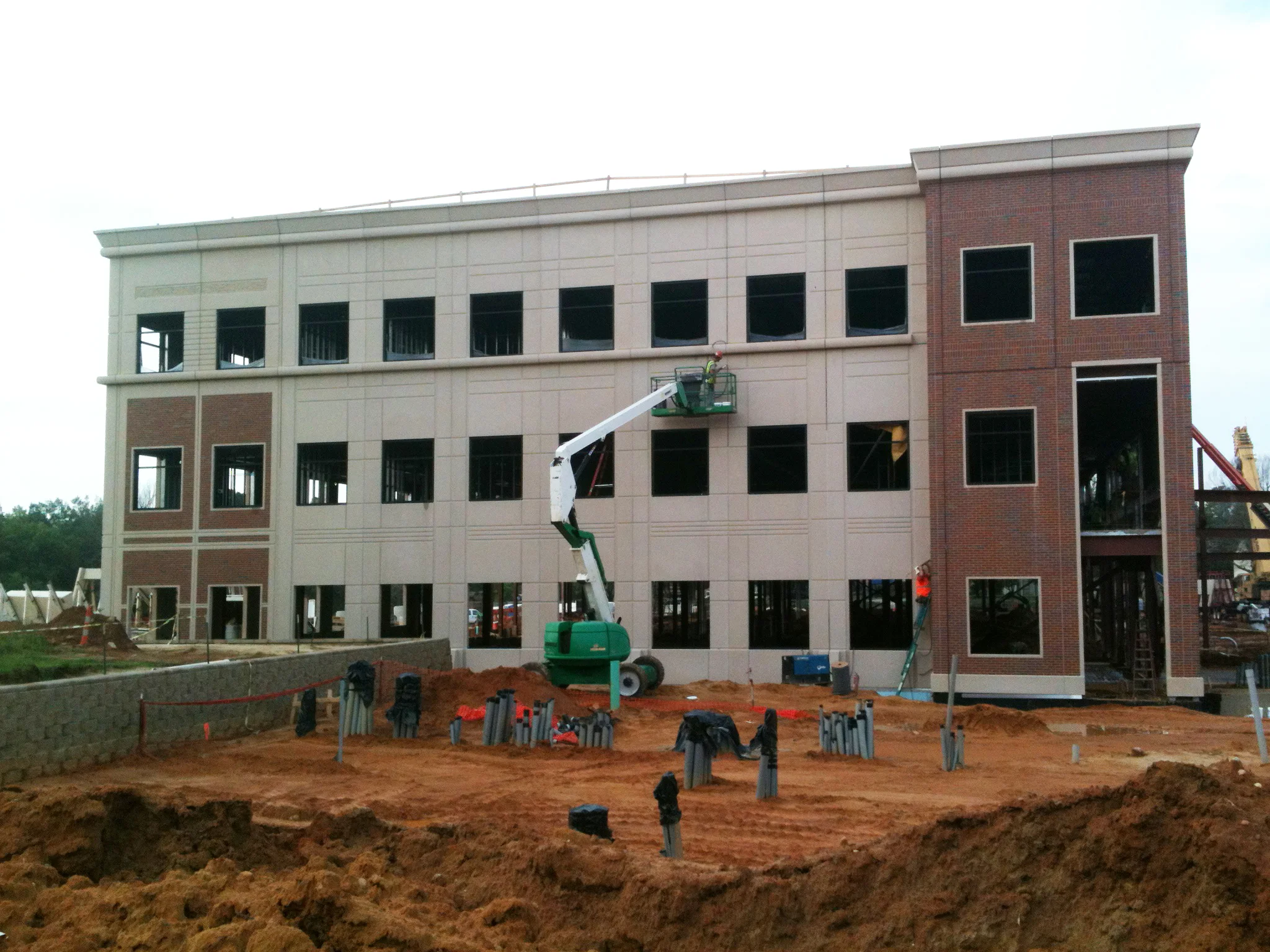
Side elevation.

SFO Air Traffic Control Tower

with Fentress Architects
as Designer

location: San Francisco, CA
typology: airport renovation
size: n/a
status: under construction

SFO Air Traffic Control Tower and Integrated Facilities is a large scale airport renovation that includes the renovation of existing terminals as well as the addition of new terminals and gates.

I prepared the schematic design plans for the Delta Sky Lounge, gate access and loading.  I also created schematic exterior massing design drawings.

In addition, I also worked on the glass clad link between the old and new terminals. I created a series of schematic renderings to develop the design and understand the space and light conditions. In addition to being a glass pass through, this renovation also incorporated the main entry to the new air traffic control tower.  

PLANS
PLANS

Delta Sky Lounge, gate access and loading plans.

EXTERIOR SKETCHES
EXTERIOR SKETCHES

Delta Lounge massing studies.

RENDERING
RENDERING

The link and approach to the air traffic control tower.

RENDERING
RENDERING

Link glass façade.

Office of the Chief, Army Reserve

with Fentress Architects
as Job Captain / Project Designer

location: Fort Belvoir, VA
typology: office, government
size: 88,500 SF
status: construction complete


One of the most unique aspects of the Office of the Chief, Army Reserve (OCAR) project was its schedule. The epitome of a fast-track design build project, OCAR was substantially complete 365 days from award. During the proposal stage, I helped craft the concept and schedule that would allow the design team time to develop the proper construction content while concurrently creating design build packages for various stages of bid, permit and construction. Additionally, I verified the program, space planned for the required adjacencies, identified program risks and began the general concept massing. I created all of the proposal documents, plan diagrams, exterior enclosure schemes and the site concept.
As job captain and BIM coordinator I led the team in the organization and creation of documents from schematic to deisgn development. During construction documents I focused mainly on the development of the exterior enclosure, to meet the design intent and modularize the façade. My efforts reduced the amount of time needed to review shop drawings and minimized form making and production time.
Several design principles influenced the development of the concept. Home to a three star general, the facades require a level of formality. Additionally, the building housed a number of functions that needed to be accommodated. And lastly, the site bordered a historic area that valued and wanted to maintain its isolation from the building.
The design and construction of this project although challenged with a tight schedule was very successful in many regards. Communication, organization diligence and rigor produced a high quality set of documents, a high quality constructed product and surpassed our LEED requirements achieving Gold status. 

ILLUSTRATIVE SITE PLAN
PROGRAMMING DIAGRAM
PROGRAMMING DIAGRAM

Color coded program and adjacency diagram.

EXTERIOR ELEVATIONS | MOCK UP

Precast panel drawings and hybrid mockup.

CONSTRUCTION PHOTO & DIAGRAM

Complicated areas of precast detailing exploded.

EXTERIOR DETAIL CONSTRUCTION DOCUMENTS
OCAR Rendering Back 0727-ts2.JPG
OCAR Rendering Front 0727-ts2.jpg

Norfolk Consolidated Courts Complex

with Fentress Architects
as Architectural Staff

location: Norfolk, VA
typology: court house
size: Phase 1, 200,00 SF / Phase 2, 300,000 SF
status: phase 1 construction complete / phase 2 under construction

The goal of the Norfolk Consolidated Courts Complex is to combine the functions of various buildings and courts into a singular location. Because of the magnitude and number of players in this project, the process began with a series of design charrettes and presentations to various stakeholders.

The project is divided into two phases, the first will house the majority of the new courtrooms, judge’s chambers and holding areas, while the second phase will encompass more of the supports staff areas and offices. The project has also introduced a new master plan to incorporate a light rail station across the street in addition to man environmental design elements.

I began work on this project at the end of the construction documents phase.  I focused on the exterior detailing of the precast, stone, curtain wall and cornices. I also worked briefly on some interior detailing. I worked directly with the project designers as well as the design consultants whose focus was on the exterior enclosure and energy efficiency of the design.

After shelving the drawings for three years, the project restarted at the end of 2012 with bidding and construction. I returned to the project as part of the construction administrative team responding to RFIs, reviewing shop drawings, creating CCDs and ASIs and providing any additional information for construction clarification.

CONSTRUCTION PHOTO | RENDERING | SITE PLAN
PROGRAMMING PLAN
PROGRAMMING PLAN

The development of multiple circulation systems between specific functions is crucial in courthouses.

CONSTRUCTION DOCUMENTS

Exterior stone detailing at loggia and rotunda.

CONSTRUCTION DOCUMENTS

Exterior façade detailing.

Super Small Standard Embassy Design

with RTKL Associates
as Architectural Designer

location: TBD
typology: embassy
size: 30,000 SF
status: conceptual prototype


The SSSED is a prototype design exercise for an international post of thirty people.  The building is organized into three parts: the first accommodates embassy personnel and visitors; the second, an atrium acts as a separation device and the third encompasses the more secure embassy functions.

The sweeping curvature of the roof profile is accentuated by a band of copper cladding forming the overhang.  Clerestory glass areas bring into light to the central working zone. The concrete roof structure economically offers higher ceilings and an airy environment.

The nano-atrium has several roles such as a separation device, communication area and light well. Flanked by wood panel walls, the double height three-meter wide space accentuates the roof form and custom light fixtures spanning the general work area.

The rear portion of the structure is designed as a modular component to be constructed offsite and re-assembled on location. The copper cladding is attached with bowed metal trusses and interrupted by stone window surrounds. As a prototype, this project has built-in flexibility to suit various changes in climate and location. Both the roof profile and back bar cladding have been designed to include options to maintain their architectural identity yet deal with the potential of shifting conditions.

The architectural vocabulary of the embassy is carried through in the detailing of the compound entrance and receiving facility.  Both would use local materials (stone and metal) as part of their detailing.

I worked on the design of this project under the oversight of the studio design lead and created all of the documentation and renderings.

AERIAL SITE PLAN
AERIAL SITE PLAN
ENTRY OPTION
ENTRY OPTION

The concept proposed two types of roofs, flat and curved, based on climate and cost.

ENTRY OPTION
ENTRY OPTION

Curved roof option.

MODULAR COMPONENTS
MODULAR COMPONENTS

The third portion of the building was proposed as a modular composition due to the sensitivity of program.

NANO-ATRIUM
NANO-ATRIUM

Interior sectional perspective through the nano-atrium.

Coastline Hotel

with RTKL Associates
as Architectural Staff

location: Wilmington, NC
typology: Hotel
size: approx. 120,000 GSF
status: schematic design

Located on the Cape Fear River, the Coastline Hotel is conceptualized as a new nine story hotel tower attached to a 18th century single story railroad warehouse. The client requested a modern design that combined a variety of programmatic elements beyond those of a typical hotel. There would be 188 guestrooms, meeting rooms, a restaurant, two bars, a rooftop pool and live/work apartments comprising  the basic program.

The site is at the northern terminus of the city's River Walk, which when complete, will connect the city's waterfront to a revitalized industrial area. The project’s location is also adjacent to the site of the city's future convention center.

The hotel tower design utilizes the existing historic warehouse as the entry lobby with large meeting spaces, a restaurant and a bar. The unique characteristics of the warehouse are emphasized by exposing the timber trusses and existing masonry walls.  A new glass loggia will run the length of the north elevation and wood clad feature walls will support the main port-cochere and entry canopy.

The first level and mezzanine of the new hotel tower will be used for back of house functions and loft style live/work units that face the river. Floors three through eight are typical guestroom floors and the rooftop will house other amenities such as another bar, a pool, a fitness room, and private function space. The composition details of wood accents and timbers with metal cladding  offer a modern industrial aesthetic to compliment the history of the site.

My responsibilities were to  work through the design by assisting the architectural lead and modeling the project in Revit. This created the foundation for creating schematic design drawings and rendering graphics.

MASTER PLAN
MASTER PLAN
SITE PLAN
SITE PLAN
EXPLODED AXON
EXPLODED AXON

Diagram showing the important building project components.

DESIGN SECTION
DESIGN SECTION

Wooden loggia adjacent to existing railroad warehouse.

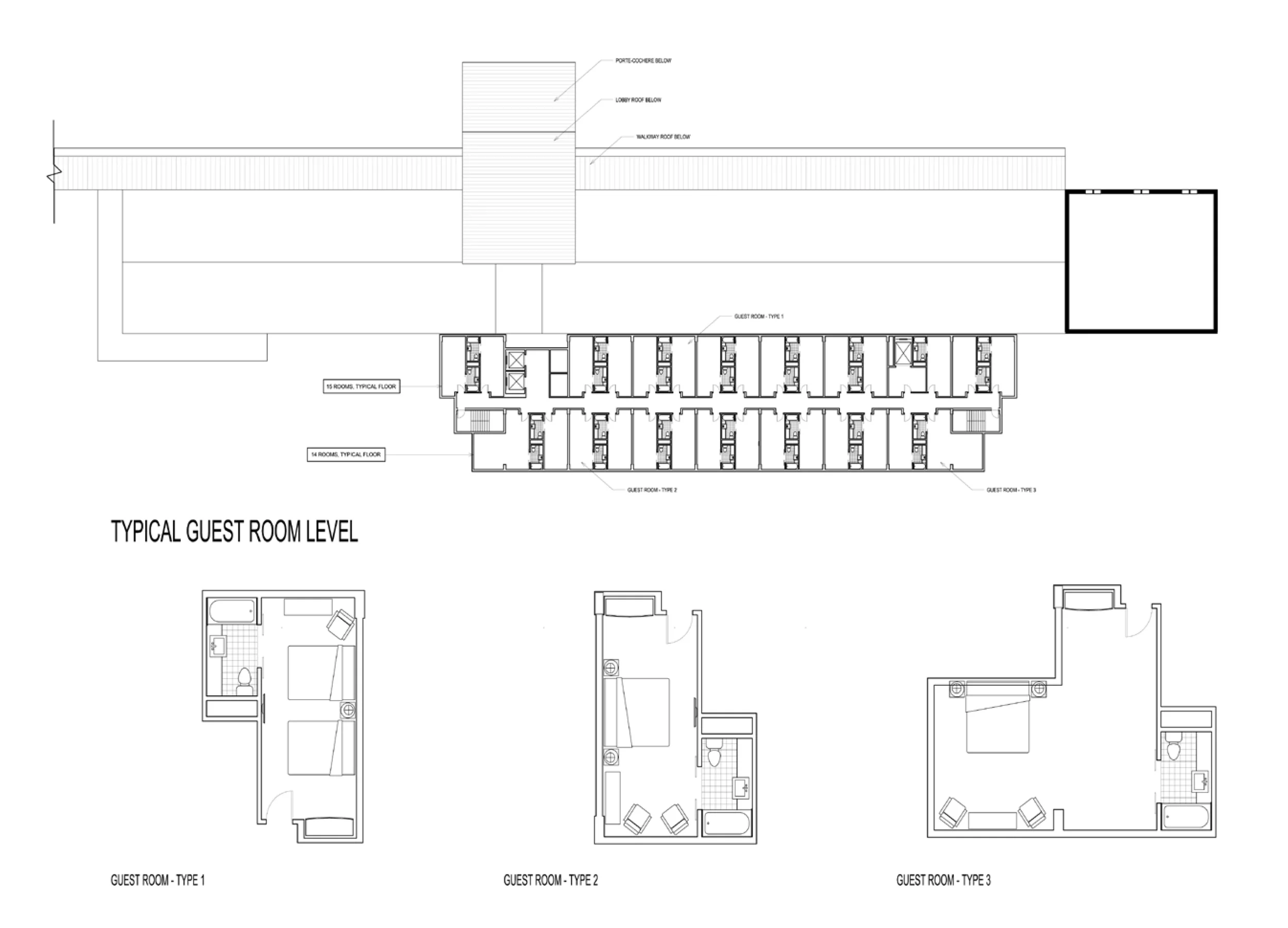
TYPICAL GUESTROOM FLOOR PLAN
TYPICAL GUESTROOM LAYOUTS

The building organization lent itself to three different standard layout types.

OVERALL BUILDING IMAGES

Overall bu

RENDERING
RENDERING

Sawyer Residence

with Architect 31 LLC
as Lead Designer / Project Architect

location: Copake Lake, New York
typology: Residential
size: 2000 SF
status: concept design

The Sawyer residence is a single family home situated on an acre of lakeside land sloping aggressively toward the water.  The existing structure is a small single story clapboard home built in the mid-1980's.  The topography exposes the lower level of the backside of the house. 

The client envisions this home as a retreat from the bustle of their permanent home in New York City and desires to expand the house to include more bedrooms, a larger indoor/outdoor living space and to update the finishes to a more contemporary palette.

prev / next
Back to Professional Projects
4000 cover image - title1.jpg
8
4000 Connecticut Building Renovation
dcjcc cover image - title.jpg
9
District of Columbia Jewish Community Center
tacc COVER IMAGE-title.jpg
7
Turkish-American Community Center
nga COVER IMAGE-title2.jpg
9
National Geospatial-Intelligence Agency
82nd COVER IMAGE-title1.jpg
6
The Headquarters of the 82nd Airborne Division
82nd COVER IMAGE-title2.jpg
4
SFO Air Traffic Control Tower
ocar cover image - title2.jpg
7
Office of the Chief, Army Reserve
nccc COVER IMAGE-title.jpg
4
Norfolk Consolidated Courts Complex
SSSED COVER IMAGE-title.jpg
5
Super Small Standard Embassy Design
coastline COVER IMAGE-title1.jpg
8
Coastline Hotel
sawyer COVER IMAGE-title1.jpg
4
Sawyer Residence

Contact | www.linkedin.com/in/adrianazarrillo